KMIDS Veloz Self-Driving Car (WRO 2026)
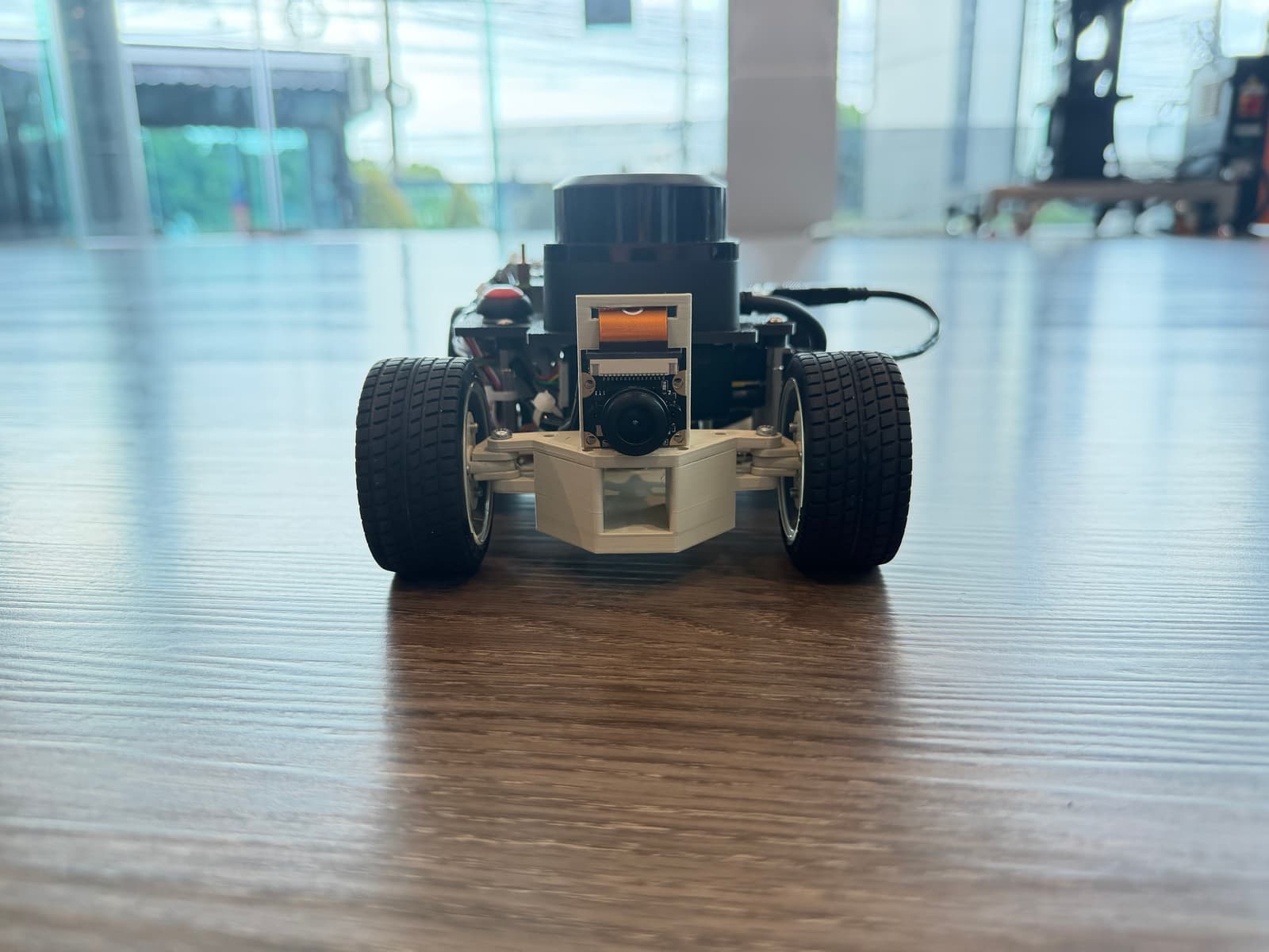
An autonomous vehicle built by KMIDS Veloz for the WRO Future Engineers 2026 competition, navigating open and obstacle challenges with LIDAR and camera sensing.
- Self-driving 1:10
- Open source
- 3D printable
Suggested by Robotheca, created by @phonpaaaa (opens in a new tab), from github.com/phonpaaaa/KMIDS-Veloz-FutureEngineer2026 (opens in a new tab). Pinned to commit 7aaf78f (opens in a new tab).
- Hardware license
- MIT (opens in a new tab)
- Software license
- MIT (opens in a new tab)
- Commercial use
- Allowed
Photo
- Power
- 12 V
- Weight
- 80 g
- Height
- 59 mm
What it can do
Written by Robotheca from the project's documents.
- Drives autonomously through the WRO Future Engineers Open Challenge and Obstacle Challenge without wall contact.
- Uses a reactive LIDAR controller reacting to four distance sectors (front, left, right, back) to steer and set speed.
- Detects green and red pillars with a front camera and passes them on the correct side.
- Performs a parallel-parking maneuver into an unknown bay in the Obstacle Challenge.
- Splits computing: Raspberry Pi 5 handles perception and navigation, Pico 2 drives motor and steering from received commands.
- Monitors battery state of charge and can shut down gracefully at a minimum battery level.
Bill of materials
15 parts15 of 15 parts shown
| # | Component | Quantity | Est. price | Supplier |
|---|---|---|---|---|
| 1 | Single-board computer | 1 | – | – |
| 2 | Microcontroller | 1 | – | – |
| 3 | PCIe adapter | 1 | – | – |
| 4 | LIDAR | 1 | – | – |
| 5 | Camera | 1 | – | – |
| 6 | IMU | 1 | – | – |
| 7 | Drive motor | 1 | – | – |
| 8 | Steering servo | 1 | – | – |
| 9 | Power/UPS module | 1 | – | – |
| 10 | Drivetrain gearing | 1 | – | – |
| 11 | Rear axle rod | 1 | – | – |
| 12 | Motor driver | 1 | – | – |
| 13 | Power switch | 1 | – | – |
| 14 | Start button | 1 | – | – |
| 15 | Camera wire | 1 | – | – |
15 of 15 parts have no price in the source, so there is no parts total. Read from README.md at the pinned commit.
Build guide
The guide appears here as you scroll.
Guide by @phonpaaaa (README.md), under MIT.
Wiring and electronics
Notes written by Robotheca from the project's documents.
Main parts
- Raspberry Pi 5 single-board computer for perception and navigation.
- Raspberry Pi Pico 2 microcontroller for motor, servo and telemetry control.
- RPLidar S3 360-degree LIDAR for distance sensing.
- Fish-eye camera with 640x480 at 30 fps capture for pillar detection.
- BNO085 IMU for orientation sensing.
- 20GP-180 DC gearmotor with quadrature encoder for driving the rear wheels.
- Motor driver circuit between the Pico 2 and the drive motor.
- Surpass Hobby S0009M digital servo for steering.
- UPS module reporting battery state over I2C, feeding a 5V logic rail, with motor power stepped up to 12V.
- Physical power switch on the battery/UPS pack.
Connections
- Raspberry Pi 5 is the I2C master and the Pico 2 is an I2C slave on the link between the two boards.
- The Pico 2 sends PWM and direction signals to the motor driver, which powers the 20GP-180 motor.
- Encoder signals from the 20GP-180 motor are wired back to the Pico 2 encoder inputs.
- The steering servo is driven by PWM directly from the Pico 2.
- The UPS module reports battery state over I2C on register 0x17.
- The 5V logic rail powers the Raspberry Pi 5, Pico 2, camera, IMU and LIDAR; motor power is stepped up to 12V separately.
Cables and connectors
From the parts list.
- Camera wire × 1

