Desktop Robot Arm
A compact 3D-printed desktop robot arm with a rotating base and gripper, controlled through a browser joystick over its own Wi-Fi access point.
- Robot arm
- Open source
- arduino
- 3D printable
Suggested by Robotheca, created by @cancast (opens in a new tab), from github.com/cancast/Desktop-Robot-Arm (opens in a new tab). Pinned to commit f797ef3 (opens in a new tab).
- Hardware license
- MIT (opens in a new tab)
- Software license
- MIT (opens in a new tab)
- Commercial use
- Allowed
Photo and 3D model
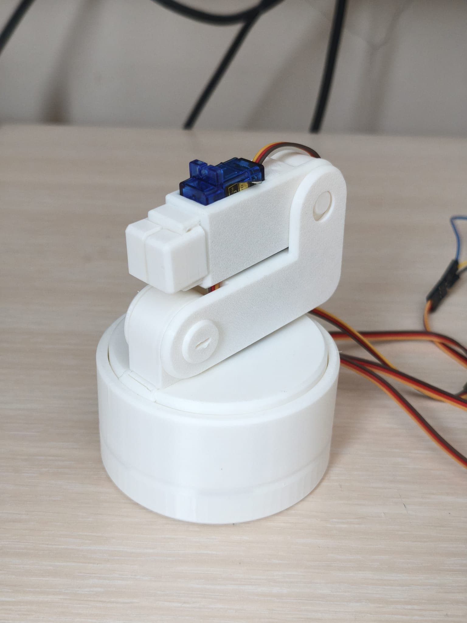
3D model loaded from the original files on GitHub at f797ef3, under MIT. View the original files from GitHub (8.5 MB) (opens in a new tab)
- Power
- 5 V
What it can do
Written by Robotheca from the project's documents.
- Rotates its base and moves its arm under control from a browser-based two-axis on-screen joystick.
- Joystick X axis drives the rotating base; Y axis drives both arm motors; a Gripper button opens and closes the gripper.
- Motors stop automatically when the joystick is released.
- Hosts its own Wi-Fi access point and serves the control page, so no router or internet connection is needed.
- Built from 3D-printed body, arm, transmission and gripper parts using ring gears in the base and helical gears in the arm.
Bill of materials
This repository has no parts list Robotheca can read yet.
Build guide
The creator's steps, each with its instructions.
- 1Install the arm and gripper servos, then join the geared arm modules
- 2Fit the gear cover and lower arm brace, then secure the joints with printed fast
- 3Attach the arm to the rotating platform and install its retaining clip
- 4Install the base-rotation servo and drive gear, then join the rotating platform
- 5Install the two gripper jaws and their synchronizing gear
- 6Turn every joint by hand and check that the gears move freely before connecting
The guide appears here as you scroll.
Guide by @cancast (README.md), under MIT.
More guides
Wiring and electronics
Notes written by Robotheca from the project's documents.
Main parts
- ESP32-C3 Mini development board as controller.
- Three continuous-rotation SG90 servo motors for the base and arm movement.
- One 180 degree positional SG90 servo motor for the gripper.
- Regulated 5 V, 3 A external power adapter for the servos.
- DC barrel-jack screw terminal, breadboard and jumper wires.
Connections
- Base rotation servo signal connects to ESP32-C3 GPIO 5.
- Arm servo 1 signal connects to GPIO 6; arm servo 2 signal connects to GPIO 7.
- Gripper servo signal connects to GPIO 8.
- Servos are powered from the 5 V external supply via the breadboard VCC and GND rails, not from the ESP32 3.3 V pin.
- The ESP32 ground and the servo supply ground are connected together to share a common reference for the PWM signals.
