ASTRA
An open-source 9.5 kg quadruped robot with a 3-DoF active spine, designed to be rebuilt for around €1500 and used to study active spine control.
- Quadruped
- Open source
- ROS 2
- 3D printable
Suggested by Robotheca, created by @fedecomi04 (opens in a new tab), from github.com/fedecomi04/opensource-spinal-quadruped (opens in a new tab). Pinned to commit 41dab01 (opens in a new tab).
- Hardware license
- Apache-2.0 (opens in a new tab)
- Software license
- Apache-2.0 (opens in a new tab)
- Commercial use
- Allowed
Photo and 3D model
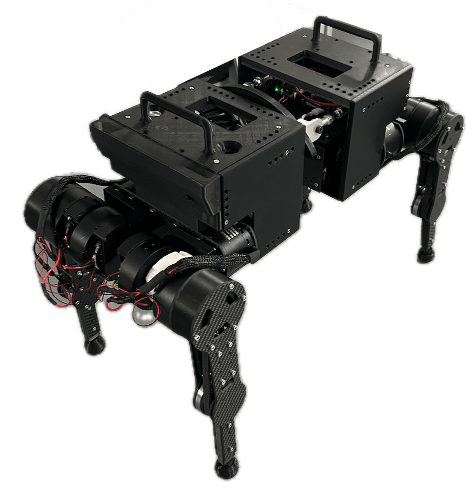
3D preview converted from github.com/fedecomi04/opensource-spinal-quadruped at 41dab01, under Apache-2.0. View the original files from GitHub (24.6 MB) (opens in a new tab)
- Degrees of freedom
- 15
- Power
- 24 V
- Height
- 435 mm
- Weight
- 9.5 kg
What it can do
Written by Robotheca from the project's documents.
- Balances its body horizontally on an inclined plane by actively rotating a 3-DoF spine, keeping either the front or rear body level.
- Performs a hard-coded trot gait with quintic foot trajectories and inverse kinematics, reaching about 4 cm/s on hardware.
- Allows single-motor command for hardware bring-up and boot-time joint zeroing.
- Can be run in a MuJoCo simulation that exposes the same ROS 2 topics as the real hardware.
Bill of materials
This repository has no parts list Robotheca can read yet.
Build guide
The creator's steps, each with its instructions.
- 1Order the motors
- 2Cut the CFRP frame and leg parts from the STEP file
- 33D-print the Tough PLA brackets
- 4Wire the electronics
- 5Flash the firmware
- 6Set up the Pi with ROS 2 Jazzy
- 7Bring-up: zero joints, verify in MuJoCo, then walk with the trot controller
The guide appears here as you scroll.
Guide by @fedecomi04 (README.md), under Apache-2.0.
Wiring and electronics
Notes written by Robotheca from the project's documents.
Main parts
- Raspberry Pi 5 acting as the non-real-time controller running ROS 2 Jazzy.
- Two STM32H723VG boards handling the real-time CAN-FD bus, one per body half.
- 15 Damiao motors (DM6006 for hips, waist and knees; DM4010 for the spine) with on-board BLDC drivers.
- RoboMaster PDU distributing 24 V from a 6S LiPo battery to the motors.
- A separate power bank supplying the Raspberry Pi.
- An IMU providing pitch data.
Connections
- Raspberry Pi 5 connects to each STM32H723VG board over USB.
- Each STM32 board drives its motors over CAN-FD using FDCAN peripherals, at 1 Mbit/s arbitration and 5 Mbit/s data.
- Front STM32 board drives the front right and front left motors plus a motor bus; rear board drives rear motors and the spine.
- The motors receive 24 V from the PDU, while the Raspberry Pi runs from its own power bank so a kill-switch can cut motor power alone.
- Each 14-byte USB packet from the Pi is unpacked into a CAN frame, and CAN replies are repacked into USB packets for the Pi.